|
|
Introduction
ATMega8535 has USART (Universal Synchronous and Asynchronous Receiver and Transmitter), the device which can be used for serial communication. With this device, you can communicate with other hardwares. I'll show you how to communicate with PC via PC's serial port (9pin D-SUB).
About USART
USART (Universal Synchronous and Asynchronous Receiver and Transmitter) is the hardware to translate between parallel data and serial data. The main features of USART of ATmega8535 is as following.
- Full Duplex Operation
- Supports both Asynchronous and Synchronous Operation
- Supports 5/6/7/8/9 data bits
- Supports 1/2 stop bits
- Supports Odd or Even parity generation and check
- Capable of detecting data overrun
- Capable of detecting framing error
- Supports separate interrupts for TX complete/TX data register empty/RX complete
ATmega8535 uses RXD (PDIP pin-no is 14) for data receiving, TXD (PDIP pin-no is 15) for data sending. To realize serial communication, you essentially should connect these 2 pins to TXD/RXD of the serial port of your PC.
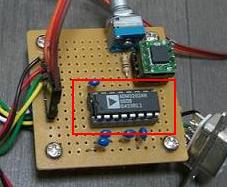
But the signal level of Atmega8535 and serial port of your PC (known as RS-232C, EIA-232, EIA-575, ...) differs in usual (0 - 5V for USART of ATmega8535, -15V - 15V for the serial port of the PC). So you need a level converter between AVR and PC. In this document I use ADM3202, RS-232 Line Drivers/Receivers.
ADM3202 is marked by a red rectangle in the photo below.

Registers
I'll show the registers we need to use USART. Pin names can be used when you use avr-libc.
- USART I/O Data Register (UDR)
Bit No. 7 6 5 4 3 2 1 0 Pin name - - - - - - - - Initial value 0 0 0 0 0 0 0 0 The UDR is the register which holds both sending data and received data.
When sending data, application should write the data to the UDR, then the data will automatically be transported to the transmit Shift Register when the register is empty. After that, the data will be output on the TXD pin. You can write to the UDR only when the UDRE flag in the UCSRA register is set, other than that the data will be ignored.
When reading data, application should read the UDR and the contents of the received data will be returned.
The width of this register is 8 bit. When the data bit length of the communication is 5/6/7, the upper bits will be ignored when sending, and set to 0 when receiving. When the data bit length of the communication is 9, upper 1 bit must be handled via the UCSRB register. I'll describe it later.
- USART Control and Status Register A (UCSRA)
Bit No. 7 6 5 4 3 2 1 0 Pin name RXC TXC UDRE FE DOR PE U2X MPCM Initial value 0 0 1 0 0 0 0 0 Pin name Description RXC (USART Receive Complete) This bit is set when there are unread data, and is cleared when you read the UDR. TXC (USART Transmit Complete) This bit is set when there are no data in the UDR. This bit is automatically cleared on Transmit Complete Interrupt. It also can be cleared manually by writing 1. UDRE (USART Data Register Empty) This bit is set when the UDR is ready to receive new data. FE (Frame Error) This bit is set when a Frame Error occures. This bit is valid until you read the UDR, so you must access this bit first before you access the UDR. You must always set this bit to 0 when writing to the UCSRA. DOR (Data OverRun) This bit is set when a Data OverRun occures. As well as the case of the FE, this bit is valid until you read the UDR. You must always set this bit to 0 when writing to the UCSRA. PE (Parity Error) This bit is set when a Parity Error occures. As well as the case of the FE, this bit is valid until you read the UDR. You must always set this bit to 0 when writing to the UCSRA. U2X (Double the USART Transmission Speed) Writing this bit to 1 and the transfer rate for asynchronous communication is doubled. Write 0 to this bit when you use synchronous operation. MPCM (Multi-processor Communication Mode) Writing 1 to this bit and the Multi-processor Communication mode is enabled.
- USART Control and Status Register B (UCSRB)
Bit No. 7 6 5 4 3 2 1 0 Pin name RXCIE TXCIE UDRIE RXEN TXEN UCSZ2 RXB8 TXB8 Initial value 0 0 0 0 0 0 0 0 Pin name Description RXCIE (RX Complete Interrupt Enable) Writing 1 to this bit enables interrupt on the RXC flag. TXCIE (TX Complete Interrupt Enable) Writing 1 to this bit enables interrupt on the TXC flag. UDRIE (USART Data Register Empty Interrupt Enable) Writing 1 to this bit enables interrupt on the UDRE flag. RXEN (Receiver Enable) Writing 1 to this bit enables the USART Receiver. TXEN (Transmitter Enable) Writing 1 to this bit enables the USART Transmitter. UCSZ2 (Character Size) The combination of this bit and 1-0 bit of the UCSZ1 determines the number of data bits in a communication frame. RXB8 (Receive Data Bit 8) Ninth data bit of the received data is set when the number of data bits in a communication frame is set to 9. Read this bit before you read the UDR for the low bits. TXB8 (Transmit Data Bit 8) Ninth data bit of the sending data is set when the number of data bits in a communication frame is set to 9. Write this bit before you write the UDR for the low bits.
- USART Control and Status Register C (UCSRC)
Bit No. 7 6 5 4 3 2 1 0 Pin name URSEL UMSEL UPM1 UPM0 USBS UCSZ1 UCSZ0 UCPOL Initial value 1 0 0 0 0 1 1 0 The UCSRC register is mapped to the same I/O address with the UBRHH register. When you write to the UCSRC, The URSEL bit of the UCSRC register must be 1. To read the content of the UCSRC, you must read UBRRH first. Then you should read UCSRC at the next clock cycle. This read sequence must be atomic. So make sure that no interrupts will occur during the read sequence.
Pin name Description URSEL (Register Select) You must set this bit to 1 before you write to the UCSRC. UMSEL (USART Mode Select) USART asynchronous operation is selected when this bit is set to 0. Synchronous operation is selected when this bit is set to 1. UPM1/UPM0 (Parity Mode) The combination of the UPM1 and the UPM0 determines the Parity Mode. UPM1 UPM0 Parity Mode 0 0 Disabled 0 1 Reserved 1 0 Even Parity 1 1 Odd Parity USBS (Stop Bit Select) When this bit is set to 0, the number of stop bits will be 1. The number of stop bits will be 2 when this bit is set to 1. UCSZ1/UCSZ0 (Character Size) The combination of the UCSZ1/UCSZ0 and the UCSZ2 bit of the UCSRB register determines the number of data bits in a communication frame. UCSZ2,1,0 Character Size 0,0,0 5 bit 0,0,1 6 bit 0,1,0 7 bit 0,1,1 8 bit 1,0,0/1,0,1/1,1,0 Reserved 1,1,1 9 bit UCPOL (Clock Polarity) The settings of this bit is applied when the synchronous mode is selected. The UCPOL bit determines the relationship between data output/input and the synchronous clock (XCK). UCPOL Transmitted Data Changed Received Data Sampled 0 Rising XCK Edge Falling XCK Edge 1 Falling XCK Edge Rising XCK Edge
- USART Baud Rate Registers (UBRRH and UBRRL)
The UBRR register holds the baud rate setting. The setting is 12 bits width, 4 most significant bits must be written to the UBRRH register, and the 8 least significant bits must be written to the UBRRL register. The baud rate setting can be calculated by following equations.
Operating Mode Equation to calculate UBRR Asynchronous Normal Mode ((System Oscillator clock frequency)/(16 * BAUD)) - 1 Asynchronous Double Speed Mode (U2X = 1) ((System oscillator clock frequency)/(8 * BAUD)) - 1 Synchronous Master Mode ((System oscillator clock frequency)/(2 * BAUD)) - 1 --- UBRRH ---
Bit No. 7 6 5 4 3 2 1 0 Pin name URSEL "reserved" "reserved" "reserved" - - - - Initial value 0 0 0 0 0 0 0 0 As I described at the UCSRC register part, UBRRH register is mapped to the same I/O address with the UCSRC register. When you write to the UBRRH, the URSEL bit of the UBRRH register must be 0.
Pin name Description URSEL (Register Select) This bit must be set to 0 when you write to the URSEL. USART Baud Rate Register 4 most significant bit of the baud rate setting. --- UBRRL ---
Bit No. 7 6 5 4 3 2 1 0 Pin name - - - - - - - - Initial value 0 0 0 0 0 0 0 0 Pin name Description USART Baud Rate Register 8 least significant bits of the baud rate setting.
Circuit diagram
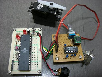
Here is the circuit diagram. RXD/TXD of ATmega8535 are connected to R1OUT/T1IN of ADM3202. And R1IN/T1OUT of ADM3202 are connected to TXD/RXD of 9pin D-SUB. According to these connections, data flow will be as following.
| data from PC | TXD(9pin D-SUB) -> R1IN(ADM3202) -> R1OUT(ADM3202) -> RXD(ATmega8535) |
|---|---|
| data from ATmega8535 | RXD(9pin D-SUB) <- T1OUT(ADM3202) <- T1IN(ADM3202) <- TXD(ATmega8535) |
Sample program
I'll show you a sample program of serial communication using USART. You can download the source code from here. You also can download it as a tar archive of all the sample programs at this page.
This source code contains the following.
- Makefile
- util.h
- util.c
- usart.h
- usart.c
- main-int.c (main function when you use rx complete interrupt)
- main-noint.c (main function when you do not use rx complete interrupt)
util.h/util.c are the same with those I showed at LECTURE 2 Make LED blink. Makefile is a bit changed but is easy to understand. So here, I'll show you other 4 files below. All the source code is distributed under modified BSD license (new BSD license). See the License. Licenses for documentation and source code are described there.
If you've never done fuse bits configuration, do "make fuse" first. See the description of the sample program at LECTURE 2 Make LED blink for the "make fuse".
If you want to upload the program which uses rx complete interrupt, do "make uisp-int". If you want to use the program which does not use rx complete interrupt, do "make uisp-noint". What these 2 programs do is the same. Just the way of implementation is different.
This sample program runs with the following parameters.
- Asynchronous operation
- Baud rate is 9600 bps
- no parity check
- 1 stop bit
- 8 bits data
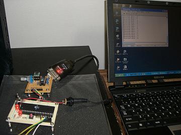
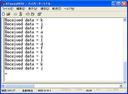
Connect the board with the serial port of your PC (9 pin D-SUB) using a straight cable. Set above parameters to your favorite terminal soft, and make connection without flow control. Once the connection is established, press any key with a printable character on the PC, and you'll get the strings like "Received data = ..." on your terminal console. "..." is replaced with the character you pressed.


- usart.h
1 #ifndef ___USART_H_INCLUDED_ 2 #define ___USART_H_INCLUDED_ 3 4 #include <inttypes.h> 5 6 7 /* Definition of macros to select if you use rx complete interrupt or not. */ 8 #define USART_NO_INT 0 9 #define USART_USE_INT 1 10 11 12 void usart_set_rx_interrupt(void (*func)(void)); 13 void usart_init(int use_interrupt); 14 int8_t usart_rx_char(void); 15 void usart_tx_char(int8_t c); 16 void usart_tx_string(char *string); 17 18 19 #endif 20 21 /* End of usart.h */- line 4
You need to include inttypes.h, a header file of avr-libc, to use some types like int8_t in function prototype.
- line 7 - 9
Definition of macros to select if you want to use rx complete interrupt or not in usart_init(). I'll describe about usart_init() later.
- usart.c
1 #include <avr/interrupt.h> 2 #include <avr/io.h> 3 #include <inttypes.h> 4 5 #include "usart.h" 6 7 8 /* Baud rate (bps) */ 9 #define USART_BAUD 9600 10 11 12 static void (*rx_interrupt_handler)(void); 13 14 15 /* 16 * rx complete interrupt handler called by avr-libc. 17 * This will be enabled when the macro USART_USE_INT is specified to usart_init(). 18 */ 19 ISR(USART_RX_vect) 20 { 21 rx_interrupt_handler(); 22 } 23 24 25 /* 26 * The setter of user function 27 * which will be called from rx complete interrupt handler. 28 */ 29 void 30 usart_set_rx_interrupt(void (*func)(void)) 31 { 32 rx_interrupt_handler = func; 33 } 34 35 36 /* 37 * Sets the USART parameters to 9600bps/8N1. 38 * 39 * When the program will use rx complete interrupt, 40 * call sei() after executing this function (usart_init()). 41 */ 42 void 43 usart_init(int use_interrupt) 44 { 45 /* Calculates the baud rate parameter to set UBRR to. Equation is (F_CPU/(16*BAUD)) - 1 */ 46 uint16_t baud = (F_CPU / (16UL * USART_BAUD)) - 1; 47 48 UBRRH = (uint8_t)(baud >> 8); 49 UBRRL = (uint8_t)baud; 50 51 if (use_interrupt) { 52 /* Enables TX/RX/rx complete interrupt */ 53 UCSRB = _BV(TXEN) | _BV(RXEN) | _BV(RXCIE); 54 } 55 else { 56 /* Enables Tx/Rx */ 57 UCSRB = _BV(TXEN) | _BV(RXEN); 58 } 59 } 60 61 62 /* 63 * Receives 1 character. 64 * Returns -1 when the framing error or overrun occurred. 65 */ 66 int8_t 67 usart_rx_char(void) 68 { 69 loop_until_bit_is_set(UCSRA, RXC); 70 71 if ((UCSRA & _BV(FE)) || (UCSRA & _BV(DOR))) { 72 return -1; 73 } 74 75 return UDR; 76 } 77 78 79 /* 80 * Sends 1 character. 81 */ 82 void 83 usart_tx_char(int8_t c) 84 { 85 loop_until_bit_is_set(UCSRA, UDRE); 86 UDR = c; 87 } 88 89 90 /* 91 * Sends character string. 92 */ 93 void 94 usart_tx_string(char *string) 95 { 96 while (*string != '\0') { 97 usart_tx_char(*string); 98 string ++; 99 } 100 } 101 102 103 /* End of usart.c */- line 1
We need avr/interrupt.h to define the interrupt handler specified at line 19.
- line 8 - 9
The baud rate is defined to 9600bps.
- line 15 - 22
If the rx complete interrupt is enabled, the interrupt handler defined here will be called. Interrupt handlers should be defined as follows when using avr-libc.
ISR(MACRO_EXPRESSES_INTERRUPT_TYPE)
{
        /* Write the body of interrupt handler here... */
}
The macros corresponding to the types of interrups are defined in avr/interrupt.h. Here I use USART_RX_vect which means USART rx complete interrupt of ATmega8535.
- line 25 - 33 (usart_set_rx_interrupt())
Registers the user function which will be called from USART rx complete interrupt handler.
- line 36 - 59 (usart_init())
Initializes the functions of USART. First we calculate the UBRR value correspond to the baud rate using the formula I already explained at Registers. The set the UBRRH/UBRRL to the calculated value.
The default values of other registers means the following.
- Asynchronous operation
- no parity check
- 1 stop bit
- 8 bits data
I set the TXEN / RXEN bit of the UCSRB register to 1 to enable USART communication. When we use rx complete interrupt, we also should set the RXCIE bit to 1. To make rx complete interrupt start to be triggered, we must call sei(), defined in avr/interrupt.h, to enable interruption itself.
- line 62 - 76 (usart_rx_char())
Reads 1 data from the receiving buffer.
First we should wait till the RXC bit of the UCSRA register be set to 1 (means unread data exists in the buffer). loop_until_bit_is_set(sft, bit) is the macro to wait by busy loop till the specified bit of the specified register be set to 1. You need to include avr/io.h to use the macro.
When you detect the completion of the receiving, check the FE and DOR bit of the UCSRA register to make sure neither data overrun nor framing error occurred. If the either of it occurred, returns -1.
After that, reads the UDR register to get the received data from the buffer.
- line 79 - 87 (usart_tx_char())
Puts 1 data to the send buffer. First we should wait till the UDRE bit of the UCSRA register be set to 1 (means the send buffer is empty). Then write the data to the UDR register and returns. The data will automatically be sent in background.
- line 90 - 100 (usart_tx_string())
Sends the specified string, by sending each character one by one using usart_tx_char().
- main-int.c (uses rx complete interrupt)
    1    #include <avr/interrupt.h>
    2    #include <avr/sleep.h>
    3    #include <inttypes.h>
    4
    5    #include "usart.h"
    6    #include "util.h"
    7
    8
    9    static void rx_interrupt(void);
   10
   11
   12    int
   13    main(void)
   14    {
   15            pullup();
   16            usart_init(USART_USE_INT);
   17            usart_set_rx_interrupt(rx_interrupt);
   18            sei();
   19
   20            while (1) {
   21                    sleep_mode();
   22            }
   23
   24            return 0; /* avoids warning... */
   25    }
   26
   27
   28    static void
   29    rx_interrupt(void)
   30    {
   31            char buf[20] = "Received data =  \r\n";
   32            int index = 16;
   33
   34            int8_t recv_data = usart_rx_char();
   35
   36            if ( recv_data == -1 ) {
   37                    usart_tx_string("Unknown data...\r\n");
   38                    return;
   39            }
   40
   41            buf[index] = recv_data;
   42            usart_tx_string(buf);
   43    }
   44
   45    /* End of main-int.c */
main() which uses rx complete interrupt is defined in this file.
- line 12 - 25 (main())
First, this function processes the following sequence.
- pullup() (pullup.h, enables internal pullup of all the input ports)
- usart_init() (usart.h, initializes USART)
- usart_set_rx_interrupt() (usart.h, registers the user function which will be called when rx complete interrupt occurred)
Then main() calles sei() defined in avr/interrupt.h to enable interrupts. Right after this, rx_interrupt() (I'll explain this later) will be triggered every time USART receives data.
After calling sei(), main() enters the while-loop which never returns. Data transmission via USART is handled in rx_interrupt() through rx complete interrupt.
sleep_mode() at line 21 is the function to move AVR into sleep mode. sleep_mode() is defined in avr/sleep.h. There are several modes in sleep mode, and you must specify the mode beforehand by set_sleep_mode() if necessary.
#include <inttypes.h>
#include <avr/sleep.h>

void set_sleep_mode(uint8_t mode);
void sleep_mode(void);
You can choose one of the following sleep mode by set_sleep_mode().
arg sleep mode SLEEP_MODE_IDLE Idle mode SLEEP_MODE_ADC ADC noise reduction mode SLEEP_MODE_PWR_DOWN Power down mode SLEEP_MODE_PWR_SAVE Power save mode SLEEP_MODE_STANDBY Standby mode SLEEP_MODE_EXT_STANDBY Extended standby mode Refer to the datasheet of ATmega8535 for more details. In the main() above, no mode is specified explicitly, so the default sleep mode (SLEEP_MODE_IDLE) will be used.
- line 28 - 43 (rx_interrupt())
First, rx_interrupt() receives 1 character by usart_rx_char(). Because rx_interrupt() is executed within rx complete interrupt handler and the RXC bit of the UCSRA register is already set, usart_rx_char() returns immediately. If either data overrun or framing error occurred (usart_rx_char() returns -1), rx_interrupt() sends the string "Unknown data..." by usart_tx_string() and returns. If valid data is received, sends the string "Received data = ..." (received data value is embedded).
By the way, avr-libc has sprintf() / snprintf(), the popular c library functions, but I don't use those library functions and put the received data value directly into the buffer to make the string to send. Actually I wanted to use sprintf() / snprintf(), but when I linked my program using sprintf() / snprintf() to avr-libc, the size of the program exceeded 8 KB, which is the flash memory size of ATmega8535 (even it is optimized). That's why I'm not using those functions. If I'm making some mistakes, someone please let me know...
- main-noint.c (without rx complete interrupt)
    1    #include <inttypes.h>
    2
    3    #include "usart.h"
    4    #include "util.h"
    5
    6
    7    int
    8    main(void)
    9    {
   10            char buf[20] = "Received data =  \r\n";
   11            int index = 16;
   12
   13            pullup();
   14            usart_init(USART_NO_INT);
   15
   16            while (1){
   17                    int8_t recv_data = usart_rx_char();
   18
   19                    if (recv_data == -1) {
   20                            usart_tx_string("Unknown data...\r\n");
   21                            continue;
   22                    }
   23
   24                    buf[index] = recv_data;
   25                    usart_tx_string(buf);
   26            }
   27
   28            return 0; /* avoids warning... */
   29    }
   30
   31    /* End of main-noint.c */
main() which does not use rx complete interrupt is defined in this file.
- line 7 - 29 (main())
First, this function processes the following sequence.
- pullup() (pullup.h, enables internal pullup of all the input ports)
- usart_init() (usart.h, initializes USART)
Then main() enters the while-loop. In this loop, main() does the same process of rx_interrupt() defined in main-int.c. The different thing is that usart_rx_char() will block while the receiving buffer is empty in this case.
It must be fun to see your custom circuit board communicating with PC through the connected cable !
