|
|
Introduction
Here, as our start point, I'm going to show you how to make LED connected to AVR blink.
I/O ports
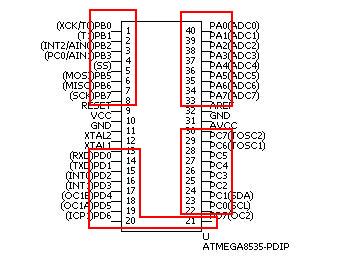
To light LED, we must connect LED to the I/O ports of ATmega8535. ATmega8535 has 4 I/O ports (A-D), and each port has 8 pins. In case of PDIP package, pin NO. of each port is as following.
- PORTA : 40 (PA0) - 33 (PA7)
- PORTB : 01 (PB0) - 08 (PB7)
- PORTC : 22 (PC0) - 29 (PC7)
- PORTD : 14 (PD0) - 21 (PD7)

We can use several names to specify the same pin when we use avr-libc. In this document, when I want to specify PA0 as an input pin for example, I use PINA0. Also when I want to specify PA0 as an output pin, I use PORTA0. The same rule will be applied to the other pins.
Registers
Each I/O port has three registers correspond to the role of output/direction/input. See below. Please replace X to the real port identifier (A-D). Pin names I'll show can be used when you use avr-libc.
- Port X Data Register (for output) (PORTX)
Bit No. 7 6 5 4 3 2 1 0 Pin name PORTX7 PORTX6 PORTX5 PORTX4 PORTX3 PORTX2 PORTX1 PORTX0 Initial value 0 0 0 0 0 0 0 0
- Port X Direction Register (to specify data direction) (DDRX)
Bit No. 7 6 5 4 3 2 1 0 Pin name DDX7 DDX6 DDX5 DDX4 DDX3 DDX2 DDX1 DDX0 Initial value 0 0 0 0 0 0 0 0
- Port X Input Pins Address (for input) (PINX)
Bit No. 7 6 5 4 3 2 1 0 Pin name PINX7 PINX6 PINX5 PINX4 PINX3 PINX2 PINX1 PINX0 Initial value N/A N/A N/A N/A N/A N/A N/A N/A
When you use I/O ports, configure data direction via Direction Register (DDRX) first. If you want to use a certain pin as an input, then write 0 to corresponding bit of DDRX. Write 1 if you want the pin as an output. After that, you can drive output pin by writing 1 (High) or 0 (Low) to the corresponding bit of PORTX. If you use the pin as an input, read the corresponding bit of PINX.
You can enable pull-up registers by writing 1 to input configured pin. This will prevent you from excessive current consumption when the pin is unused/unconnected.
Circuit diagram
Here is the circuit diagram. We're going to light the LED connected to PB0 pin of PORTB. The LED will be lit when PB0 pin is driven high.
Sample program
Now I'm going to show you a simple program that make LED blink. You can download the source code here. You also can download it as a tar archive of all the sample programs at this page.
This source code contains the following.
- Makefile
- util.h
- util.c
- main.c
I'll show you these below. All the source code is distributed under modified BSD license (new BSD license). See the License. Licenses for documentation and source code are described there.
If you've never done fuse bits configuration, do "make fuse" first. "fuse" target will do the following.
uisp -dprog=dapa -dlpt=0x378 --wr_fuse_l=0xff
This target will set the low byte of fuse bytes of ATmega8535 to 0xff. By this, we can use 8MHz external crystal as a clock source. If you don't do this, 1MHz internal RC oscillator will be used as the default clock source.
fuse bits configuration will be saved, so this target must be executed just once. See LECTURE 1 Overview of ATmega8535 and the environment we use for the description of fuse bits.
To compile and upload your program, execute the following.
make
make uisp
"uisp" target will do the following.
uisp --dprog=dapa -dlpt=0x378 --erase --upload --verify
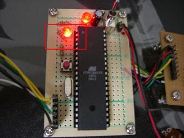
This means uisp will erase the contents of the flash memory, upload the specified program, verify the uploaded program data. If you see no error, your program succsesfully uploaded and the LED will start to blink. ON/OFF status of LED will change in every 250ms.

The video uploaded to YouTube is here.
- Makefile
1 CC = avr-gcc 2 OBJCOPY = avr-objcopy 3 4 UISP = uisp -dprog=dapa -dlpt=0x378 --erase --upload --verify 5 FUSE = uisp -dprog=dapa -dlpt=0x378 --wr_fuse_l=0xff 6 7 MCU = atmega8535 8 FORMAT = ihex 9 F_CPU = 8000000 10 11 CFLAGS = -Wall -std=gnu99 -mmcu=$(MCU) -Os -DF_CPU=$(F_CPU) 12 13 %.o: %.c; $(CC) -c $(CFLAGS) -o $@ $< 14 %.hex: %.elf; $(OBJCOPY) -O $(FORMAT) $< $@ 15 16 OBJS = main.o util.o 17 ELFS = main.elf 18 TARGET=main.hex 19 20 all: $(TARGET) 21 main.hex: main.elf 22 23 main.elf: $(OBJS) 24 $(CC) $(CFLAGS) -o $@ $^ 25 26 main.o: main.c util.h 27 util.o: util.c util.h 28 29 uisp: main.hex 30 $(UISP) if=$< 31 32 fuse: 33 $(FUSE) 34 35 clean: 36 rm -f $(TARGET) $(ELFS) $(OBJS) *~ - util.h
1 #ifndef ___UTIL_H_INCLUDED_ 2 #define ___UTIL_H_INCLUDED_ 3 4 #include <avr/io.h> 5 6 7 #define pullup() {\ 8 PORTA = 0xff; \ 9 PORTB = 0xff; \ 10 PORTC = 0xff; \ 11 PORTD = 0xff; \ 12 } 13 14 void delay_250ms(void); 15 16 17 #endif 18 19 /* End of util.h */- line 7 - 12 (pullup())
pullup() macro will drive all the I/O ports of ATmega8535 High (write 1 to all pins). If there are unconnected I/O ports, there might be excessive current consumption. To prevent this, we'll enable pull-up register of all pins.
- util.c
1 #include <util/delay.h> 2 #include "util.h" 3 4 5 void 6 delay_250ms(void) 7 { 8 int i; 9 10 for (i = 0; i < 25; i ++) { 11 _delay_ms(10); 12 } 13 } 14 15 /* End of util.c */- line 5 - 13 (delay_250ms())
delay_250ms() waits 250ms properly. _delay_ms() is defined by avr-libc.
void _delay_ms(double _ms);
_ms : Specify time period you want to wait in milli seconds.
This macro depends on the system clock frequency. You have to define F_CPU macro to use _delay_ms(). In this document, I prepared F_CPU macro in Makefile as following.
F_CPU = 8000000
8000000 means 8MHz. According to the documentation of avr-libc, the maximum value you can specify to _delay_ms() is calculated by 262.14ms / F_CPU(MHz). In this case it will be about 38ms. Counting this, I call _delay_ms(10) 25 times and the delay of 250ms is accomplished.
- main.c
1 #include <avr/io.h> 2 #include "util.h" 3 4 5 int 6 main(void) 7 { 8 /* Only PB0 pin is configured as an output */ 9 DDRB = _BV(PORTB0); 10 pullup(); 11 12 while (1){ 13 PORTB ^= _BV(PORTB0); 14 delay_250ms(); 15 } 16 17 return 0; /* To avoid compiler warning */ 18 } 19 20 /* End of main.c */- line 1
I'm including avr/io.h to use some convenient macros.
- line 5 - 18 (main())
At line 9, PORTB0 pin is configured as an output by _BV() macro. DDRB is the direction register of port B. _BV() macro returns the value which the specified bit is set to 1 (all the other unspecified bit stays at the original value). This macro is defined in avr/io.h.
By executing pullup() macro at line 10, only PORTB0 will be driven high as an output and pull-up registers of all the other pins will be enabled. LED will be on because PORTB0 is now driven high.
At line 12 - 15, blinking of LED will be processed.
PORTB ^= _BV(PORTB0);
at line 13 reverse the status of PORTB0. The "^=" operator means EOR, so the result will be 0 when PORTB is 1, ant the result will be 1 when PORTB0 is 0. After reversing the status of the LED, wait 250ms by calling delay_250ms() and then goes back to the process of reversing the status of the LED.
Now I bet you can see how it's easy for you to write a program just to make LED blink. It must be so simple like this!
