|
|
Introduction
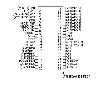
A lot of micro controllers exist in AVR series manufactured by Atmel. In this document, we're going to use ATmega8535 because I wanted A/D converter and rather large memory. Following sections describe the overview of ATmega8535, and the hardware/software environment we use.
Overview of ATmega8535
Main features of ATmega8535 are as below (not all the features).
- RISC Architecture
- 32 general purpose working registers
- 8K bytes in-system programmable flash memory
- 512 bytes EEPROM
- 512 bytes SRAM
- 8-bit timer/counters x 2 and 16-bit timer/counter
- 4 PWM channels
- 10-bit ADC (A/D converter)
- Serial USART
- Programmable wathdog timer
- 6 sleep modes
- Operating voltages : 4.5 - 5.5V
- Speed grades : 0 - 16 MHz
Fuse bits
Fuse bits is the area to save basic configurations (I don't know the exact hardware structure...). In this document, there is little opportunity to use fuse bits. We just use it to have ATmega8535 run with the external crystal oscillator.
There is a fuse high byte and a fuse low byte. We use fuse low byte to specify the clock source. The mapping of each bit is as following.
| Bit name | Bit No | Description | Default value |
|---|---|---|---|
| BODLEVEL | 7 | BOD (Brown out detector) trigger level | 1 |
| BODEN | 6 | BOD (Brown out detector) enable | 1 (BOD disabled) |
| SUT1 | 5 | Select start-up time | 1 |
| SUT0 | 4 | 0 | |
| CKSEL3 | 3 | Select clock source | 0 |
| CKSEL2 | 2 | 0 | |
| CKSEL1 | 1 | 0 | |
| CKSEL0 | 0 | 1 |
Select start-up time with the combination of SUT1 and SUT0. In this document, we'll set (SUT1,SUT0) to (1,1). Clock source is determined with the combination of CKSEL3 - 0. We'll set (CKSEL3,CKSEL2,CKSEL1,CKSEL0) to (1,1,1,1). See the table below.
| CKSEL3 - 0 | Select clock source | |||||||||||||
|---|---|---|---|---|---|---|---|---|---|---|---|---|---|---|
| 0000 | External clock | |||||||||||||
| 0001 - 0100 | Calibrated internal RC oscillator (default value is 0001, it means we use 1.0MHz internal RC oscillator) | |||||||||||||
| 0101 - 1000 | External RC oscillator | |||||||||||||
| 1001 | External low frequency crystal | |||||||||||||
| 1010 - 1111 | External crystal/ceramic resonator. The range of operating frequency would be determined with the combination of CKOPT bit of fuse high byte (default value is 1) and CKSEL3 - 1.
In this document, we're going to use 8MHz external crystal. I don't want to program the fuse high byte (this means we use the default value of CKOPT bit, 1), so CKSEL3 - 1 must be 111. It's also necessary to set CKSEL0 and SUT1 - 0 depends on the combination of the type of the external clock source and the start-up time when recovering from the sleep mode or when resetting the system. In this document, we set CKSEL0 to 1 and SUT1-0 to 11, which means we use external crystal and slowly rising power. |
We'll use an open source software named "uisp" to configure fuse bits.
Hardware environment
In this document, we use PDIP package of ATmega8535.

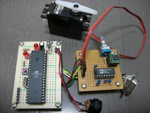
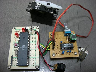
Following photo is the circuit board I built for the experiment.

Here is the circuit diagram.
ATmega8535 can run at the maximum frequency of 16MHz. If you change the frequency from 8MHz to other value, you also should change the configuration of fuse bits, and the every part of each sample programs which depends on the system clock.
I'm using a 5V AC adapter as the power supply of this circuit board.
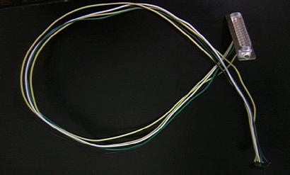
To connect PC and the circuit board, we use DAPA (Direct AVR Parallel Access) cable.

Actually, there seem to be a lot of interfaces to connect PC and AVR. DAPA cable above looked the easiest way to me so I'm using this way. Here is the diagram of DAPA cable. We'll configure fuse bits/upload our own program to AVR through this cable. To realize this, we use the open source software named "uisp".
Software Environment
In this document, we use C language to write our program, and avr-gcc on Linux ® platform to compile those source code. Please introduce following programming tools.
- GNU Binutils
This is the software which provides basic programming tools like assembler/linker, etc. In this document, we're going to use version 2.17. After downloading it, do as the following.
cd [The top directory of the source tree of binutils]
./configure --target=avr --program-prefix='avr-' --disable-nls; make
su
make install
- GCC
World-famous compiler collection which GNU is maintaining. We use version 4.1.2 in this document. Install it as following.
cd [The top directory of the source tree of gcc] ./configure --target=avr --program-prefix='avr-' --enable-languages=c \ --with-dwarf2 --disable-nls --disable-libssp; make su make install - AVR LibC
This is the libc for AVR architecture. Version 1.4.5 is required in this document. Install it as following.
cd [The top directory of the source tree of avr-libc]
./configure --build='./config.guess' --host=avr; make
su
make install
- uisp
This software is very useful to upload your own program to AVR/configure fuse bits, etc. We use version 20050207 in this document. Install it as following.
cd [The top directory of the source tree of uisp]
./configure; make
su
make install
